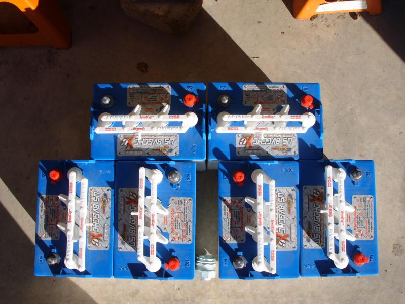
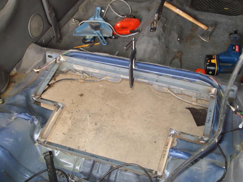
Starting with the physical battery layout.... note that I left room in the middle for the cable conduit to come into the battery case. Designing the rails I added in thickness for the rails and the 1/4" polyproplene sheeting I will line the case with. The first step was to weld up the bottom of the tray, and use it to project the outline onto the floor. Note that later I found out it would have been quicker to layout the two sections as simple rectangles and weld together rather than doing just the outline which involved careful work at the corners.
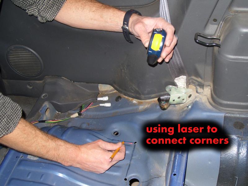
The first step was to position the front rail of the rack tray under the car... I drilled three holes in the floor along the front seat rail which is nice and flat and straight. Using a plumb bob under the car I centered and lined up the bottom tray on the floor. After marking corners right on the floor, I used the plumb to find the corners UP on the floor, and drilled holes to locate. Then, I connected the dots with marker on top. Basically, the controlling point that you need to be careful with is interfering with the brake/fuel lines in the front driver's side corner. The rear of the rack was JUST clear of the suspension; there is not a lot of extra room under there.
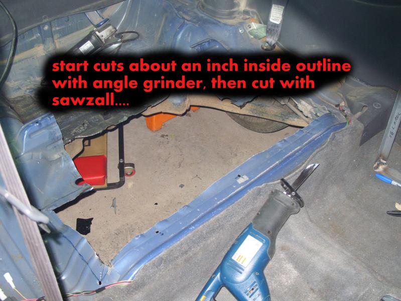
I found that starting the cuts a good inch or so inside the edges with an angle grinder was the best way to make a slot long enough to get the sawzall started. ZING! Man, that metal is thin, and the sawzall just zips right thru!
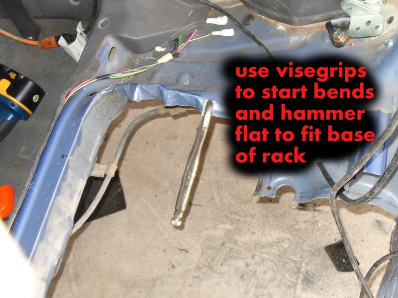
The next step was to bend down the extra material to get out to my 'outside' edge. I folded with visegrips, hammered, and worked along the edges until I could drop the rack straight down into the hole...
I decided to add some cross bracing at this point... no way that the polypro floor would hold the weight across the middle without it. After some time making elaborate cuts, welding and grinding, I sort of kicked myself for not having built the two simple rectangular 'rows' of the battery tray and then welding them together rather than the much more elaborate cutting required to do the outline first. ah well..... next one!
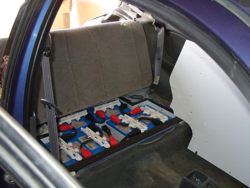
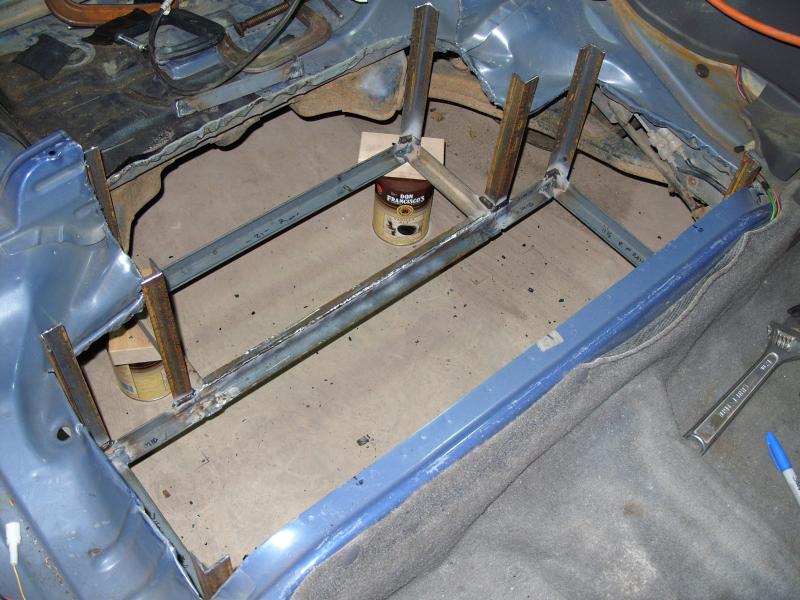 The next step was to weld on the vertical rails at the corners and attempt to figure out where to attach so the rack hangs level at a height that will leave ground clearance AND hopefully not come up too high into the cabin to make the rear seat unusable! After measuring the basic floorpan, lowest points of suspension, and evaluating how much the top of the pack would stick up into the cabin, I decided to work with a ground clearance of about 7 inches, which is about what some of the other low-hanging stuff is. A coffee can with a block on top is just about right. Turns out that the height works well to rest the front edge lip right on the seat bulkhead which is nice and flat. It hangs a little bit low, but not a bad trade-off for the good mounting rail and maintaining reasonable headroom.
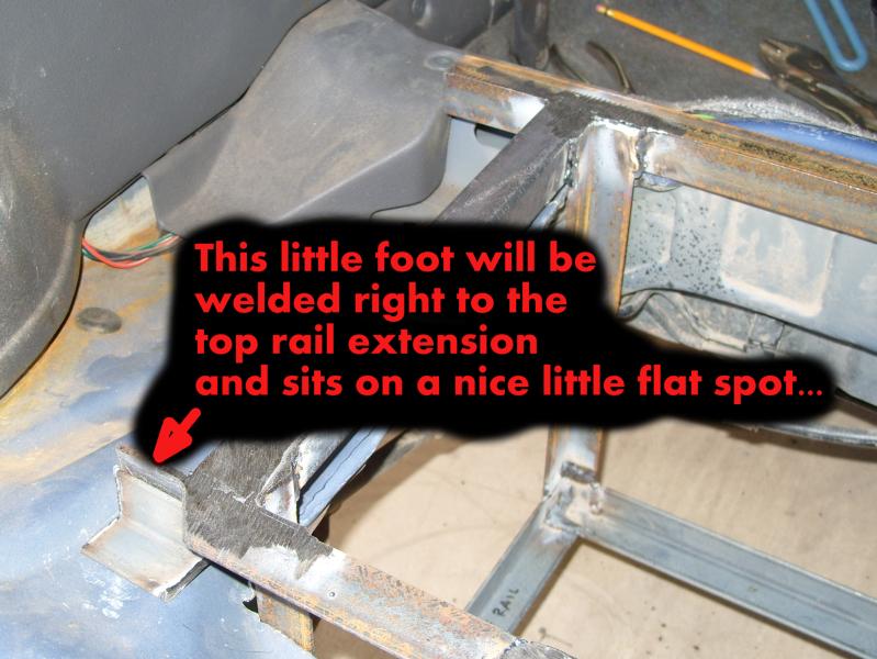 I then started around the perimeter of the top adding angle iron... with some of the pieces extending to the sides over areas with bulkhead support underneath. I was thinking that I could add some verticals and flat 'feet' to bolt or screw thru the floorpan. I tried welding one little spot; not possible with my stick welder without burning holes right through! Brazing might work, a MIG welder would probably be best, but I dont have equipment for that, so will probably bolt or screw. I purchased several different types of 'rivet nuts'...
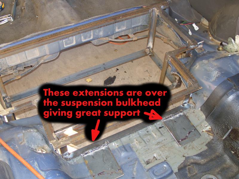 After adding little vertical tabs near the middle section, the rack was feeling pretty solid. But, I was still a little uncomfortable with attempting just a 1" wide lip bolted to one layer of sheet metal, so I added rear plates to extend the rear rail mounting over the lower suspension bulkhead. This added a few pounds, but makes the rack REALLY solid. It would probably be best to powdercoat, but its pretty dry in Santa Fe, so I am going with primer and spray-on undercoating before adding the plastic liner. The weight of the steel rack is right around 30#.
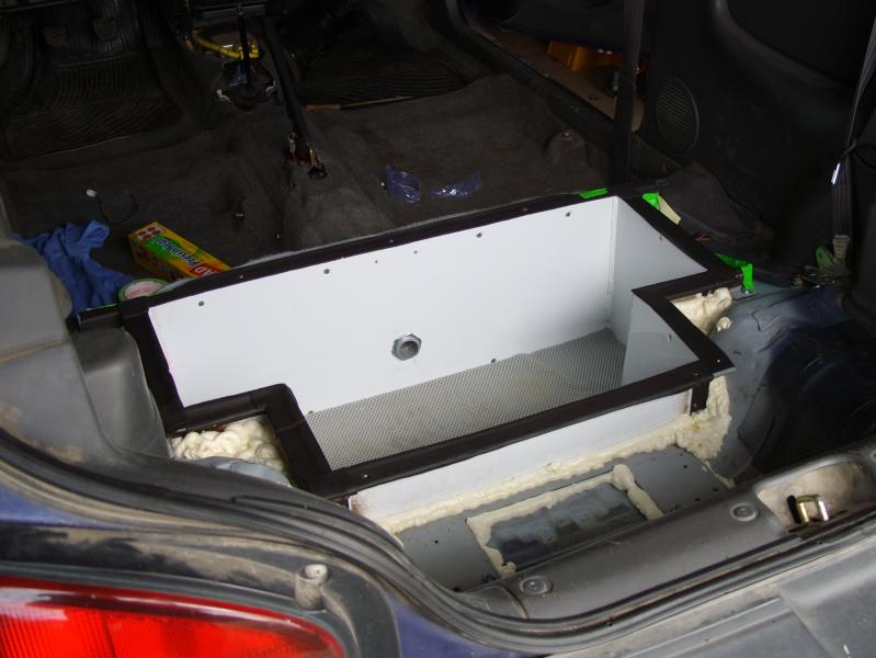
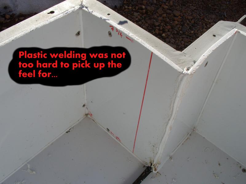 It took a while, and made a horrific mess of tiny plastic chips everywhere cutting plastic panels, drilling, tapping, and installing panels to the steel rails... The plastic itself was pretty easy to work with; I used a skil saw for most of the straight cuts, and a coarse jig blade for the corners on the cover. The 'welding' of the corners was pretty easy and came out fairly neatly. I wanted the corners sealed to prevent gaps allowing hydrogen into the cabin, and plan to use some type of weatherstripping between the rails and the top. I'll drill a small hole near the bottom, and then another as high as possible venting to the outside to allow gases to vent. The rack with plastic installed weighs in right at 40#. Plus about another 5# for the top lid. I'm sure this is a bit of a net gain since the section of the floorpan I cut out and the bottom seat foam probably weigh less than 45#.
Time to layout base and design bottom tray: .5 hr
cut and weld bottom rails : 2 hr
locate and transfer outline to floor : 1 hr
cut and bend floor : 2.5 hr
add vertical, top rails, mounting tabs, paint : 10.75 hr
plastic box fabrication and install : 6.5 hr
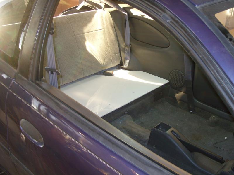
install rear seat back, lid, and seat belts : 1.0 hr
======
total : 23.75 hrs