|
Upgrading the Suzuki Swift (Geo Metro/Pontiac Firefly)... to Lithium
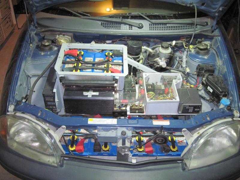
This is the last picture of the engine bay with Floodies in place... they had gotten to the point where they only had about 60% of original range, and it was getting to the point where eeking out the 20 miles I need a lot of days was causing stress and concern, so I decided to move ahead with upgrade to lithium. After one more pass thru my numbers I convinced myself that it really was cost effective to move to LIFePO4, yeilding a cost per mile down around $0.06 including electricity, compared to closer to $.13 on lead, or $.09 on gasoline at $2.75/gallon. So I decided that since I would have a little extra room to work with since I only need 100ah cells to get the range I need, I would bump up the voltage to 120v (38 cells) to match the max. voltage rating for my motor and controller. Better performance and range in the same space! This did however mean that I had to change dc-dc convertor and charger. I also ditched analog voltmeter, ammeter, and battery SOC gauges as I needed accurate amp-hr counter for lithium SOC.
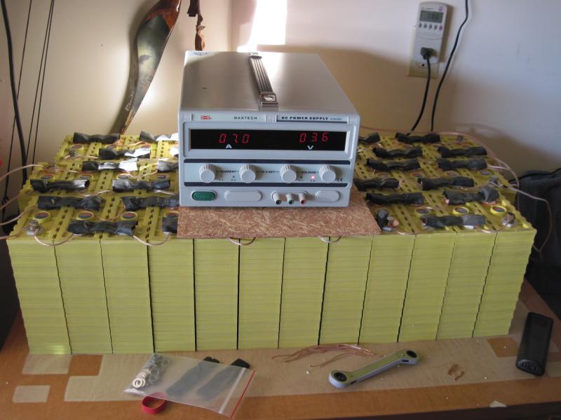
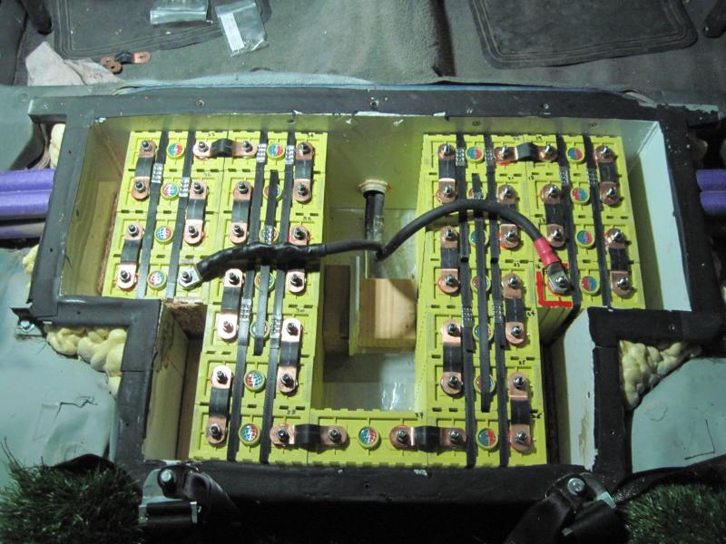
The long lead-time step is obtaining the cells, and deciding what you want to do regarding balancing and a BMS, or not. In my case I was a victim of the now infamous 'James Morrison battery fraud' in which he (EVComponents.com) took a bunch of people's money, and never delivered the batteries. You'd think a simple consumer fraud case would be a slam-dunk, but the legal system moves slowly.... Anyway, I did buy a second set of cells from a reputable dealer, and decided that I would do an initial 'top-balance' charge, and run WITHOUT a BMS. In a nutshell, I think a top-balance enables the pack to behave correctly using a charger set with a standard Li charge curve and not overcharge anything as long as the cells remain in balance. I am confident that I can manually steer clear of potential over-discharge issues given my normal range requirements of about 20 miles are well within the likely max range of the pack which is probably closer to 55 miles. So this picture shows the pack, wired in parallel, and being brought up to 3.80 volts before install and series connection. My inexpensive $139 Mastech power supply puts out a max of 10 amps, so it took 'a while', like about two weeks, to trickle in the 5 or 6kWh to bring the cells up to full! I plan to manually check balance for a while, and see how it goes. For the new charger I settled on an Elcon HF/PFC 1500 for $515 from EvolveElectrics.com as it accepts both 110vAC/220vAC input, outputs a max of 15 amps (closer to 10) so as not to blow any normal house outlets, and is sealed (cooled with fins). Its pretty efficient, but the fins get HOT after charging at 9 or 10amps for a while! Also turns out it has a pack voltage output that can be used to interlock the ksi to potbox and thence to controller. It outputs pack voltage when NOT plugged in, but zero when plugged in, so you can't drive off while plugged in. The requested curve was pre-selected as default, and CA->CV voltage set to a fairly conservative (for Thundersky cells) 3.65*38 = 139v. This charger is relatively 'fixed' except the ability to select different charge curved based on the nominal voltage I gave them. I don't intend to change battery pack configuration until the whole system dies.
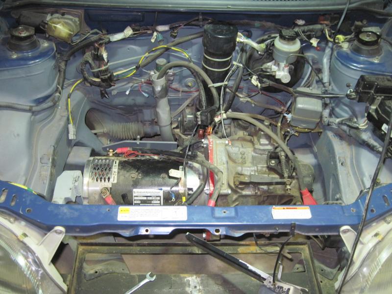
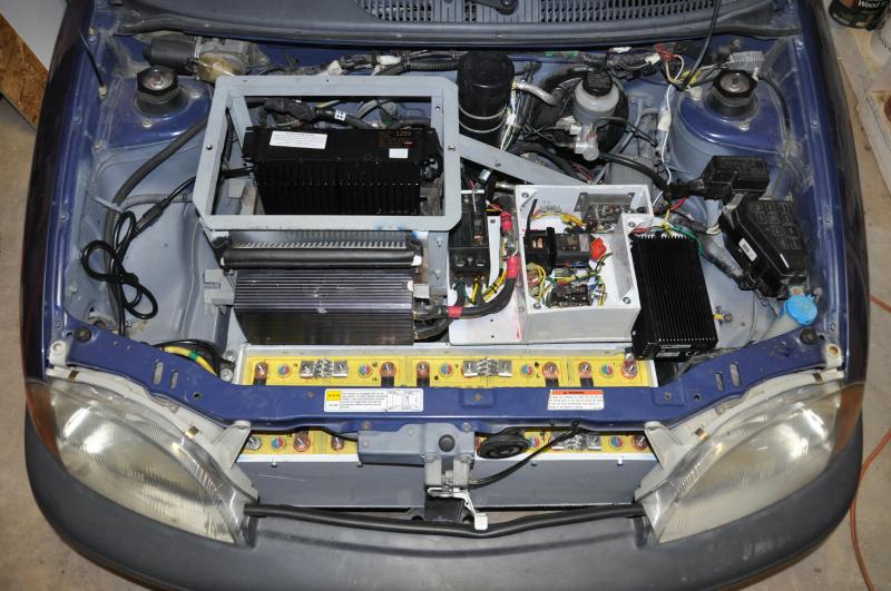
This is the motor bay after yanking all the FLA and pulling my 'component shelf'. I ended up cleaning out the fuses I had for the analog gauges and simplifying the wiring a bit. The new charger has a built-in power interlock to run thru the pot-box KSI connection to the conntroller... so I now have protection from driving while still plugged in and charging. I took a little time to clean up and tie up lots of connections to make the removal/re-install of the middle rack easy. Motor mounts and everything looked to be in pretty good shape. I did add a little sheet metal 'drip guard' over the motor ventilation intake to prevent possible rain/snow from getting sucked thru the motor as it dripped thru the back of my heat-sink vent from the hood scoop. I ground the FLA rack angle edges off the front cross member and build a front battery box from the polypro sheet I had available. I put two layers of rigid foam in the bottom for insulation, but didn't have time to install the planned heatline to warm the batteries as I was trying to get things put back together asap for a guest lecture show-and-tell at the local Santa Fe Community College. I will put in some remote thermometers to get an idea how the battery boxes do once they are enclosed.
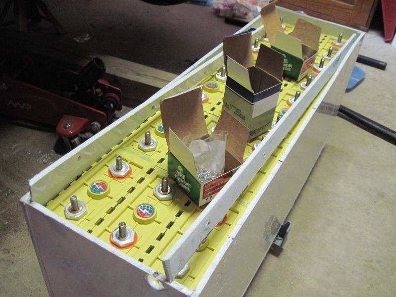
So I built the front box around the batteries as tight as I could to provide a little clamping and prevent them from rattling around, and bolted the box thru to the x-member support underneath. I decided NOT to use the regular M8 bolts, and replace with studs to guarentee full thread engagement, which is important when going in to soft terminals made from copper/aluminum! I did decide to loctite the studs in, and then use external toothed washers under nuts for all connections. The studs are 30mm long, and stick up enough (about an inch above battery) for the thickest connectors being the braided bus bars and lugged connectors. Note that M8 hardware in Aluminum or copper you should probably use a torque wrench, and no more than 20Nm (14.75 ft-pounds) to avoid stripping threads! Installing 15 x 100ah cells in the front was a tight fit behind headlight, hood latch, and clearing the motor mount, etc. The 'rails' I planned to hold the cells DOWN are ok, but don't give me a great way to fasten on a lid, so I am going to re-design a little to use wooden cross-rails, which I can then screw a top lid onto and install the whole 15 cell box as a pack. I have not decided yet, but MIGHT install monitor wires to an external terminal block to allow manual cell voltage check without removing lid.
The rear battery area now holds 23 cells, and it was interesting to lay out the connections to enable series connection around the whole area... I did use poly strap 'banding' tools to create blocks of cells for easy management. I bought a 'kit' off ebay for about $100 that really is a slick way to create 3,4,or 5 cell blocks for handling and compression. I did round the corners of the cell grooves where the straps went just to prevent stress, and it seemed to work very well...
I'll be posting some performance comparisions between the 96v lead and 120v lithium..... Initial impression is 'wow, lithium is way better!' |